

1. 서 론
2. Experimental Apparatus and Method
2.1 Experimental apparatus
2.2 Experimental method
3. Experimental Results and Discussion
3.1 Uncertainty
3.2 CHF and pool-boiling heat-transfer coefficients of graphene
4. Conclusion
1. 서 론
Nucleate boiling is one of the most important phenomena in various industries and devices such as power generations, heat exchangers, high-power electronic component cooling, and solar-collector heat pipes. Critical heat flux (CHF) refers to the upper limit of the pool-boiling heat-transfer region. Whereas, before the CHF happens, the heat-transfer coefficient is high enough to attain a sufficiently high heat
flux at a relatively low surface heat, beyond the CHF, vapor bubbles on the heating surface start to combine, forming a vapor film that greatly reduces th e heat-transfer rate between the heating surface and the liquid1). After the CHF, the heat-transfer coefficient markedly decreases with the heating surface temperature of the heat-transfer apparatus, concomitantly, is greatly increased. This incurs a risk of physical failure of the heat-transfer apparatus. Therefore, for both economic efficiency and the safety of the heat-transfer apparatus, it is vital to increase the CHF.
Many researchers have found that the CHF can be significantly increased by addition of tiny amounts of nanometer-size particles, known as nano particles, for conventional cooling liquids. Such nanofluids dispersed in a base liquid, as heat-transfer agents, have been studied in various fields of thermal engineering2). Bang and Chang (2005) confirmed a CHF increaseas high as 32% in Al2O3 nanofluid compared with base fluid3). Park and Jung (2009), tested ing the application of carbon nanotubes in nanofluid formulation using R-22 as a coolant, noted an approximately 30% heat-transfer-coefficient increase in the low heat flux section at 100 kW/m2 or less4). Liu and Liao (2008), have carried out tests on nanofluid formulated by adding CuO and SiO2 to water and C2H5OH, found that with the volume fraction of 0.01%, there could be no effect on the heat-transfer coefficient5). Golubovic et al. (2009) reported 50 and 30% CHF increases with Al2O3 and Bi2O3 nanofluids, respectively6,7). Phan et al. (2009) carried out a pool-boiling experiment on specimens coated with SiOx, TiO2, Pt, Fe2O3, SiOC, and Teflon, and reported that the contact angle and bubble-departure diameter had significant effects on the heat-transfer coefficient8). Soltanietal et al. (2010) noted in the results of a test using a nanofluid formulated by diffusing Al2O3 nanoparticles in Carboxy Methyl Cellulose (CMC) solution that the heat-transfer coefficient had decreased in the high-concentration CMC solution but had increased by about 25% in a nanofluid mixture of nanoparticles and CMC solution9). Truong et al.(2010), for the purposes of a CHF experiment, fabricated a plate heater coated by a sandblast method with diamond, zinc oxide, and alumina nanofluids10), while Ahn et al. (2010, 2013) conducted a pool-boiling CHF experiment involving anodization coating on a Zircaloy-4 surface using a plate heater11,12). The latter also carried out the same experiment using an Ni-Cr wire heater coated with 0.0005 wt.%-reduced graphene oxide, and confirmed that as the coating time increased, the CHF increased also. Most of the studies employing metallic nano-materials have reported problems such as heating-surface deposition and low nanofluid dispersibility. Phan et al. (2009) carried out a pool-boiling experiment on specimens coated with SiOx, TiO2, Pt, Fe2O3, SiOC, and Teflon. It was reported that the contact angle and the bubble departure diameter had effects on the heat-transfer coefficient13), and Yu et al. (2011) found that the thermal conductivity of ethylene glycol (EG)-based graphene nanofluid was increased 86% in a 5.0 vol% mix ratio14).
In this context, graphene, boasting a higher thermal conductivity than any other nanoparticles, has been attracting at tention as a new heat-transfer material15). Therefore, in this study, in an effort to resolve issues related to nano-material heating-surface deposition and low dispersibility, CHF and heat-transfer coefficients were measured in the pool-boiling state through the oxidation treatment of graphene.
2. Experimental Apparatus and Method
2.1 Experimental apparatus
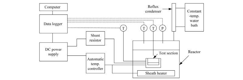
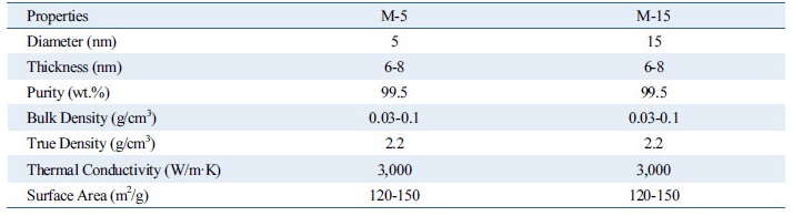
Fig. 1 is a schematic diagram of the apparatus used in this experiment. The stainless steel alloy (SUS 316)-encased reactor, which generates heat flux for the pool-boiling state, and an automatic temperature controller regulates the temperature inside the reactor. Observation of the CHF phenomenon is made possible through quartz windows of 45 mm thickness installed in the front and back of the reactor. A reflux distiller for collection of evaporated vapor, installed at the top of the reactor, is connected to a chiller that condenses the vapor for its return to the reactor. A pressure sensor of ±0.8% error and two T-type thermocouples of ±0.1℃ error are installed at the top and middle levels of the reactor, respectively, for measurement of pressure and temperature. A sheath heater of 8 mm diameter is installed at the lower level of the reactor to maintain the experimental pressure and temperature. The heat-transfer test section (37 mm × 40 mm × 30 mm) used in this experiment is composed of a zirconium (9.53 mm × 9.53 mm × 4mm). As the test section heat source, a 25 Ω heat-resistor heater (9.53 mm × 9.53 × 2.00 mm, CCR-375-1, Component General Inc.) was used. The heat-resistor heater had a 350 W maximum heat generation capacity that when combined with the zirconium specimen, a 3850 kW/m2 maximum heat flux generation capability. The zirconium specimen had three evenly spaced holes of 1 mm diameter and 4.8 mm depth, into which T-type thermocouples were inserted for temperature measurement of zirconium specimen surface. In order to isolate heat generated from the heat-resistor heater as much as possible and to supply heat only to the zirconium specimen, the heat-transfer test section for the pool-boiling heat-transfer experimentation was made of PEEK, which has a very low heat-transfer rate. A DC power supply (DAP-125, Dau Nanotek) was used to supply electric power to the pool-boiling heat-transfer test section with generated heat flux to allow for increase of the voltage and current to 125 V and 8 A, respectively (maximum : 750 W). Additionally, in order to measure the heat quantity supplied to the test section, specifically the supplied current and voltage drop, a shunt resistor (221509, Yokogawa Co.) was installed between the DC power supply and the test section. For prevention of damage to the heat-resistor at the moment of CHF occurrence from the rapid heat transfer test section temperature increase, an automatic temperature controller (NX9, Hanyoung nux) was installed to automatically disconnect the DC power supply once the temperature exceeded 155℃. A data logger (34970a, Agilent) and a computer were set up to collect and store the measured data, and a CHF measuring program was written for real-time monitoring and effective processing of the data using Labview. In this study, graphene fabricated by Chemical Vapor Deposition was used. Using graphene nanoplatelets grade M, graphene nanofluids were synthesized by sonication. The physical properties of both graphene M-5 and M-15 nanoplatelets are listed in Table 1. As indicated, they are of high thermal conductivity and purity.
2.2 Experimental method
For CHF investigation and measurement, the reactor was filled with distilled water, and a vacuum pump was used to set the experimental pressure (19.61 kPa). After confirming that the pressure of the reactor was maintained at the experimental pressure, the temperature of the distilled water was increased to the target temperature (60℃) using the sheath heater. Then, the DC power supply was connected, heating the test section in increments of 10 kW/m2 to a level sufficient for generation of heat flux. Subsequently the CHF was calculated according to convection heat-transfer Eq.(1), and the pool-boiling heat-transfer coefficient on the specimen surface along with the quantity of heat were calculated by Eqs. (2) and (3), respectively, as
 (1)
(1)
 (2)
(2)
 (3)
(3)
where A is the heat-transfer area (m2), I is the current capacity (A), Q is the supplied heat quantity (W), Tsat is the saturated temperature of distilled water (K), V is the voltage drop (V), h is the pool-boiling heat-transfer coefficient (kW/m2·K), and q″is the heat flux (kW/m2). In this case, the zirconium surface temperatures were averaged from the values measured by the three inserted T-type thermocouples. The actual zirconium specimen surface temperatures Twall were calculated by incorporating the measured average temperature Tave into the linear heat-transfer equation
 (4)
(4)
where, l is the distance from the inserted thermocouple to the surface (m) and k is the heat-transfer rate of the specimen (W/m·K)
3. Experimental Results and Discussion
3.1 Uncertainty
An analysis of the uncertainty of the data obtained in the CHF experiment in distilled water was carried out using the error propagation method of Kline and McClintock (1953)16). Heat flux and heat-transfer coefficient Equations are shown in Eq. (1) ~ (3), it can be seen that the heat flux factors are the heat-transfer coefficient and the difference between the zirconium specimen surface temperature and the working fluid temperature. The heat-transfer coefficient factors are the current, voltage drop, specimen area, specimen surface temperature, and working fluid temperature. Therefore, the heat flux and the heat-transfer coefficient can be expressed with the functions.
 (5)
(5)
 (6)
(6)
And, according to which factor, the equations for calculation of the uncertainty of the heat flux and heat-transfer coefficient results, respectively, are as follows:
 (7)
(7)
 (8)
(8)
where  ,
, ,
, ,
, ,
, ,
, ,
, and
and  are the uncertainties of the CHF, pool-boiling heat transfer coefficient, temperature difference between specimen and working fluid temperature, current, voltage drop, specimen length, specimen surface temperature, and working fluid temperature, respectively. As calculated from these equations, the uncertainties of the CHF and pool-boiling heat-transfer coefficients were ±2.2% and ±6.7%, respectively, for every fluid carried out in the study.
3.2 CHF and pool-boiling heat-transfer coefficients of graphene
Fig. 2(a) provides comparative plots of the CHFs of the graphene M-15 nanofluid and distilled water. As can be seen, the CHF as measured at the nanofluid volume fractions of 0.0001, 0.001, 0.01, and 0.1% attained the increased values of 45.45, 76.36, 129.09, and 50.90%, respectively, compared with those measured with distilled water. Clearly, these results reflected the effect of the nanofluids’suppression of vapor formation. Indeed, without the nanofluids, the vapors would have obstructed the heat transfer on the zirconium specimen surface, or prevented the small vapors from aggregating to form larger ones. However, the CHF value at the 0.1% volume fraction was lower than that at 0.01%. This indicated that the nanofluid’s volume fraction was too large, meaning that nanoparticles obstructed the transfer of distilled water between the zirconium specimen and the vapors when pool boiling occurred on the zirconium surface. Based on the results, the optimal volume fraction for enhanced CHF was determined to be 0.01%. Fig. 2(b) provides comparative plots of the pool-boiling heat-transfer coefficients of graphene M-15 nanofluid and distilled water to the point of the CHF. As shown above, both fluids increased proportionally with the increased of heat flux. The pool-boiling heat-transfer coefficients of graphene M-15 nanofluid for the 0.0001, 0.001, and 0.01% volume fractions were increased relatively to that of distilled water at the excess temperature (Twall-Tsat) by 3.05, 9.09, and 16.00%, respectively. However, for the 0.1% volume fraction, it was decreased by 0.30%.
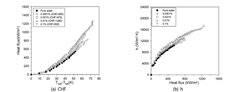
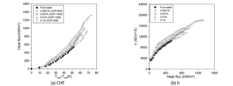
Fig. 3(a) shows comparative plots of the CHFs of the graphene M-5 nanofluid and the distilled water cases. As shown in the figure, the CHF measured at the 0.0001, 0.001, 0.01, and 0.1% volume fractions attained enhanced values of 52.73, 87.27, 145.45, and 70.01%, respectively, relative to those measured with distilled water. For the graphene M-15 nanofluid, the optimal volume fraction for enhanced CHF was determined as 0.01%. Fig. 3(b) shows comparative plots of the heat-transfer coefficients of graphene M-5 nanofluid and the distilled water to the point of the CHF. As indicated in the figure, the CHF of both fluids increased proportionally with the increas of heat flux. The heat-transfer coefficients of the graphene M-5 nanofluid for the 0.0001, 0.001, 0.01, and 0.1% volume fractions were increased by 6.25, 12.51, 22.05, and 1.36%, respectively, relative to those of distilled water at the excess temperature. Contrary to the case of graphene M-15, the pool-boiling heat-transfer coefficient at the volume fraction of 0.1% showed only a small increase.
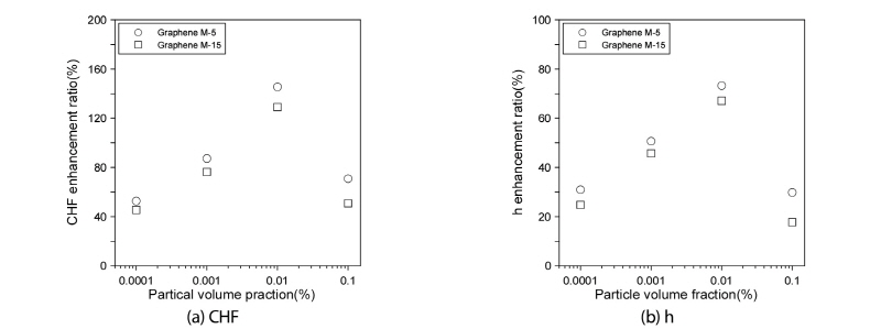
As shown in Fig. 4(a), in the case of every volume fraction, the ratio for the large-diameter graphene M-5 nanofluid was higher than that for the small-diameter graphene M-15 nanofluid. Whereas both nanofluids showed the highest CHF increase with the 0.01% volume fraction, where that of graphene M-5 was 16.36% higher than that of graphene M-15. Also, as indicated in Fig. 4(b), the heat-transfer-coefficient increase ratio for the graphene M-5 nanofluid was 9.0% higher than that for the graphene M-15 nanofluid at the 0.01% volume fraction.
3.3 CHF and pool-boiling heat-transfer coefficient of oxidized grapheme
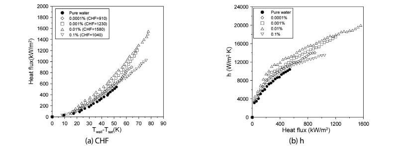
Fig. 5(a) plots the comparative CHFs of the oxidized graphene M-5 nanofluid and the distilled water. As shown in the above figures, the CHF measured at the 0.0001, 0.001, 0.01, and 0.1% volume fractions could attain the increased values of 64.45, 123.63, 187.27, and 89.09% respectively. From these results, the optimal volume fraction for enhancing CHF was determined as 0.01%. Also, the CHF curve of the oxidized and non-oxidized graphene M-5 nanofluids similar with the volume fraction of 0.1%. Also, the pool-boiling heat-transfer coefficients of the oxidized graphene M-5 nanofluid and distilled water to the point of the CHF are shown in Fig. 5(b). From these results, the pool-boiling heat-transfer coefficients of the nanofluid for the 0.0001, 0.001, 0.01, and 0.1% volume fractions were increased by 9.93, 16.44, 26.67, and 4.99%, respectively, relative to those of distilled water at the excess temperature.
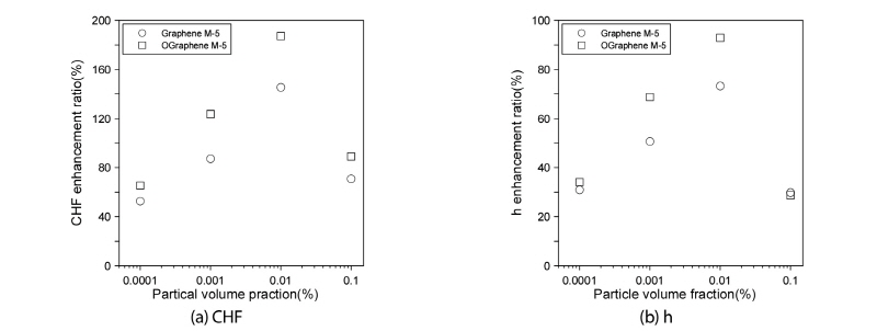
Fig. 6(a) compares the CHF-increase ratios of the oxidized graphene M-5 nanofluid and non-oxidized graphene M-5 nanofluid relative to the CHF of distilled water. As shown in the figure, at every volume fraction, the ratio for the oxidized graphene M-5 nanofluid was higher. Notably, at the 0.01% volume fraction, the CHF-increase ratio of the oxidized graphene M-5 nanofluid was 41.82% higher than that of the graphene M-5 nanofluid without oxidation treatment. Also, Fig. 6(b) compares the pool-boiling heat-transfer-coefficient increase ratios for the oxidized graphene M-5 nanofluid and the non-oxidized graphene M-5 nanofluid relative to the pool-boiling heat-transfer coefficient of distilled water at the excess temperature where the CHF of distilled water occurred. As indicated above, the pool-boiling heat-transfer-coefficient increase ratio for the oxidized graphene M-5 nanofluid was 26.7% higher at the volume fraction of 0.01%.
4. Conclusion
In the current results, both graphene M-5 and M-15 nanofluids showed the highest CHF-increase ratio at the 0.01% volume fraction. At this volume fraction, that of the graphene M-5 nanofluid was about 16.36% higher than that of the graphene M-15 nanofluid. Meanwhile, the pool-boiling heat-transfer-coefficient increase ratio of the oxidized graphene M-5 nanofluid was 9.0% higher than that of graphene M-15 nanofluid without oxidation treatment. Also, the oxidized graphene M-5 nanofluid showed a 41.82%-higher CHF-increase ratio and a 26.7%-higher heat-transfer coefficient relative to non-oxidized graphene M-5 nanofluid. Moreover, the oxidized graphene M-5 nanofluid showed a better dispersibility performance and degree of deposition. Overall, the results served to highlight the effectiveness of graphene M-5 oxidation for CHF and heat-transfer-coefficient enhancement.
