

1. Introduction
2. Experimental
2.1 Paste development
2.2 Screen printing
3. Results and Discussion
3.1 Light interference pigment
3.2 Printability
3.3 Front glazing of BIPV
4. Conclusion
1. Introduction
Climate change is becoming an increasingly serious matter in our daily lives. As a result, building integrated photovoltaics (BIPV) with a high photovoltaic (PV) conversion efficiency has garnered the attention of researchers. BIPVs are installed as the constitutional element of a building and convert solar energy into electricity1,2,3,4). It can take various forms such as the roof and skin of a building. However, public acceptance of BIPV has been poor because of its monotonous color, i.e., black. The development of colored BIPV with high aesthetic value has been necessitated by the public and the architects in urban design5,6,7). Several attempts have been made to endow BIPV with colors that are realized with multireflection coatings using a vacuum deposition process8,9,10). Monocrystalline silicon solar cells with the multiple layers of anti-reflection coatings (ARC) for green color have the averaged relative photovoltaic conversion efficiency of 85.7%11). Nanostructures can be also used for colored monocrystalline silicon solar cells with the relative photovoltaic conversion efficiency of 89 to 90%12). The one-dimensional photonic crystal layers for green color could be implemented on the front glazing rather than solar cells, resulting in the relative photovoltaic conversion efficiency of 78%13). Despite its successful development, its high manufacturing cost hinders its widespread application.
Instead of the costly vacuum deposition process, screen printing was utilized for coloring the front glazing of the BIPV by introducing a color layer14,15). Screen printing is a facile process that extrudes a paste onto a substrate through a mesh-emulsion screen with openings16) Screen printing has many advantages, such as low manufacturing cost, simplicity, and scalability. Hence, it has been used in a variety of applications16,17,18). In addition to the mesh emulsion screen itself and its printing conditions, such as speed, squeegee pressure, and snap-off distance19), a paste affects the quality of screen printing. Generally, a paste is composed of a carrier vehicle that can be a mixture of solvents, resins, and additives, and a filler material that can be an organic and/or inorganic powder. It must be formulated by adjusting its rheological properties, such as paste fluidity, thixotropy, and viscoelasticity20,21) to meet the required screen printability. Another crucial aspect of a screen-printable paste for color BIPV is pigments. Light interference pigments22), which are widely used in diverse industries, such as paint, plastics, cosmetics, and building materials23,24), exhibit excellent shine, brilliance, and vivid color effects, as investigated in a previous study25). Among the numerous types of pigments26,27,28), their semi-transparent traits may render them the most appropriate for minimizing the power loss of BIPV.
This study contributes to the formulation and evaluation of screen-printable color pastes for front glazing of BIPV. Commercially available two-part carrier vehicles and in-house developed ones were prepared and then mixed with light interference pigments to formulate screen-printable color pastes. A comparison of their screen printabilities was conducted. Finally, the aesthetic value and relative photoconversion efficiency of BIPV, where colored paste is applied, will be discussed.
2. Experimental
2.1 Paste development
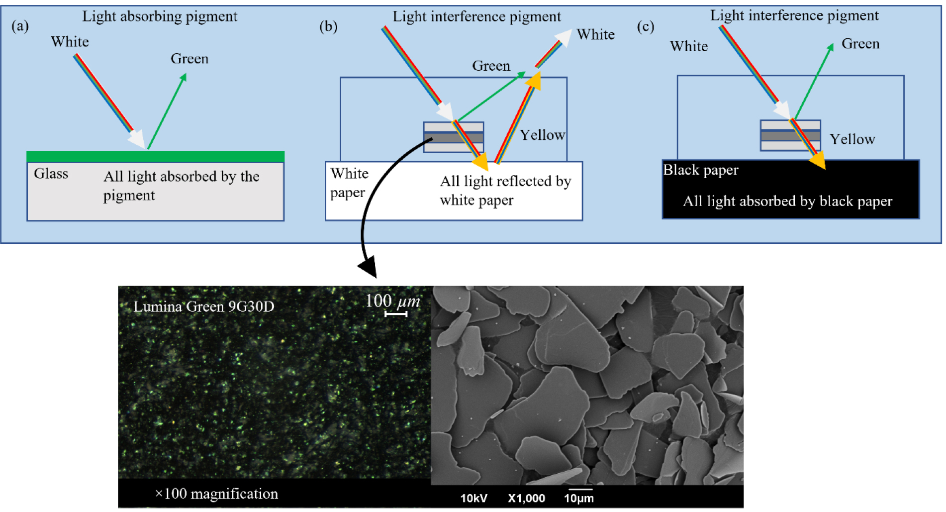
The light interference pigment used in these experiments was Lumina Green 9G30D (BASF Colors & Effects GmbH), which takes the shape of platelets with sizes ranging from 8 to 48 µm. Optical images were obtained using an optical microscope (JSZ-7XT, Samwon Scientific Industrial Co., Ltd.) at magnifications of 16 and 100. A field emission scanning electron microscope (FE-SEM) was used to obtain detailed microscopic images at a magnification of 1000 × (JSM-6700 F, Jeol, Ltd.).
Generally, a screen-printable color paste consists of filler materials, which are light interference pigments in this study, and a carrier vehicle that contains the experimental filler materials. A commercially available Crystal ClearTM 220 (Smooth-on, Inc.) was used as a carrier vehicle to formulate a colored paste because it possesses good adhesion and durability. It is a two-part curable carrier vehicle, with part A as the base material and part B as the curing agent, which needs to be mixed at a weight ratio of 100:75 for curing. It can be seen on Table 1. To make it screen printable, its viscosity must be adjusted; hence, the carrier vehicle T was formulated, which consists of terpineol (CAS No. 98-55-5, Kanto Chemical Co., Inc.) and butyl carbitol acetate (BCA) (2-(2-butoxyethoxy) ethyl acetate, CAS No. 124-17-4, Samchun Pure Chemical Co., Ltd.) as solvents and thixatrol max (Tmax ) (Elementis Specialities, Inc.) as a rheological agent. The composition of the carrier vehicle T is listed in Table 2.
Table 1
Compositions of Crystal ClearTM 220
| Classification | Composition | Weight ratio |
| Resin | Part A | 100 |
| Curing agent | Part B | 75 |
Table 2
Compositions of carrier vehicle T
| Classification | Composition | Wt% |
| Solvent | 2-(2-butoxyethoxy) ethyl acetate, i.e., BCA | 27 |
| Solvent | Terpineol | 61 |
| Rheological agent | Thixatrol Max i.e., Tmax | 12 |
To complete carrier vehicle T, terpineol and BCA were placed in a glass beaker on a heating mantle (DMB-601, Samduk Lab-Science, Corp.) and stirred using an overhead stirrer (HS-100D, Daihan Scientific Co., Ltd.) for 10 min at 500 rpm until the temperature reached 50°C. Subsequently, Tmax was added at 1000 rpm for 1 h until it was fully activated, which led to an increase in the viscosity of the carrier vehicle T. The entire process of formulating the carrier vehicle T is shown in Fig. 1.
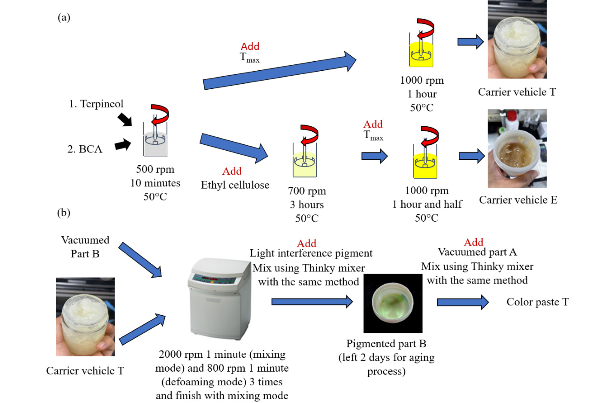
The second step involved the preparation of part B before it was mixed with the carrier vehicle T. Any bubbles in part B were first removed by placing it in a vacuum oven (DZF series, NEURONFIT Co., Ltd.) for 30 min at 0.1 bar. Subsequently, part B was mixed with carrier vehicle T using a Thinky mixer (ARE-310, Thinky Corp.), which ran consecutively in a mixing mode at 2000 rpm for 1 min, followed by a defoaming mode at 800 rpm for 1 min, and a final mixing mode at 2000 rpm for 1 min. In this manner, different versions of part B and carrier vehicle T were prepared at the weight ratios of carrier vehicle T in the range of 60 wt% and 90 wt% at increments of 10 wt%.
The experimental light interference pigments were added and homogenized with the prepared mixtures of part B and carrier vehicle T using a Thinky mixer, as described previously, and pigmented part B of Crystal ClearTM 220 was finally completed. It was left for 2 days for aging, which stabilized the pigmented part B. Before screen printing, part A, which was deaerated like part B using a vacuum oven, was mixed with pigmented part B using a Thinky mixer to avoid unwanted curing. The completed paste is referred to as paste T hereinafter.
For comparison, an in-house-developed color paste, named color paste E, was also produced, which consisted of carrier vehicle E and light interference pigments without any curing agent. Carrier vehicle E consists of solvents, a polymeric binder, and a rheological agent. First, terpineol and BCA were stirred using an overhead stirrer and heated using a heating mantle until the temperature reached 50°C. Ethyl cellulose (Product No. 200689, Sigma-Aldrich Corp.) was then added and mixed for 3 h at 700 rpm. After ethyl cellulose was completely dissolved, Tmax was added and mixed for 1 h at 1000 rpm until Tmax was fully activated. The mixing steps are shown in Fig. 1 and the weight concentrations of each ingredient are listed in Table 3.
Carrier vehicle E was mixed with a green light interference pigment in the concentration range of 5 ~ 25 wt% at increments of 5 wt%. The light interference pigment and carrier vehicle E were mixed using a Thinky mixer at 2000 rpm for 2 min (mixing mode) in the first step and 500 rpm for 1 min (defoaming mode) in the second step. These mixing steps were repeated three times, followed by a final step at 2000 rpm for 2 min (mixing mode). Subsequently, the prepared color paste E was left for 1 d at room temperature (25°C) for aging. Just before screen printing, color paste E was mixed again using a Thinky mixer, as described above, for re-homogenization. Color paste E was prepared for screen-printing.
Table 3
Compositions of carrier vehicle E
| Classification | Composition | Wt% |
| Solvent | 2-(2-butoxyethoxy) ethyl acetate, i.e., BCA | 21 |
| Solvent | Terpineol | 52 |
| Binder | Ethyl cellulose | 18 |
| Rheological agent | Thixatrol Max i.e., Tmax | 9 |
2.2 Screen printing
Screen printing is a simple procedure for extruding paste onto a rigid or flexible substrate through a mesh-emulsion screen with an opening. It is known for its low cost, simple manufacturing process, and large-scale production29). The mesh emulsion screen, squeegee, and paste work collectively to complete the screen-printing process. There were three main regions in the paste transfer during the screen-printing process. The paste flow region was where the paste was ahead of the squeegee. Paste flows in front of the nip contact because the squeegee pushes the paste during the screen printing process. The adhesion to the extension region is where the paste is stretched rather than separated. This region is behind the nip contact between the screen and substrate. Both of these regions are called the paste separation region. The flow to the separation region is where the paste is deposited onto a substrate. In this region, the paste is separated from the substrate and mesh emulsion screen after it is printed. Collectively, these three main regions are referred to as the full-contact region30) and are shown in Fig. 2.
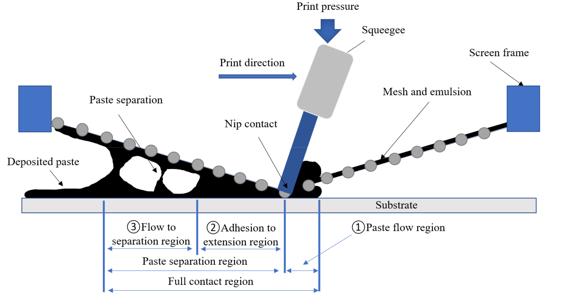
Screen-printing quality is affected by a variety of parameters, such as print speed, print pressure, snap-off distance, and the paste itself. Paste rheology determines whether high precision with fine edges can be achieved through the opening of the mesh emulsion screen. Generally, paste is composed of a filler material, solvent, polymeric binder, and rheological agent, and these individual ingredients affect the function and quality of the printed patterns. First, the filler material is a matter that helps achieve the intended function. Second, in addition to carrying a filler material or dissolving ingredients, a solvent or a mixture of solvents also acts as a diluent, allowing the paste to easily pass through the opening of a mesh-emulsion screen onto a substrate. Generally, a solvent with high volatility evaporates rapidly even before the levelling process of the printed patterns. Therefore, a solvent with low volatility is preferred because it allows more time for levelling of printed patterns before drying31). Through this levelling, the printed surface acquires smoothness or evenness. A polymeric binder promotes adhesion to ensure that the paste remains firmly on the substrate29). A rheological agent was added to adjust the rheological properties of the pastes. A desirable paste for screen-printing was achieved by adjusting these components.
A manual screen printer (S80, NamA SMT Co., Ltd.) and semi-automatic screen printer (TIGER-5335-MV, Daeyoung High Tech Co., Ltd.) were used to print the color pastes on a designated substrate. Mesh-emulsion screens with 325 mesh (20 cm × 20 cm in size, where stripe patterns were formed with an opening width of 1 mm and a pitch of 2 mm) and 200 mesh (20 cm × 20 cm in size, where the opening was formed across the entire area) were used (Daeyoung High Tech Co., Ltd.). The screen printing parameters used in this study were a snap-off distance of 1 mm, printing speed of 20 mm/s, printing pressure of 350 MPa, and squeegee angle of 65°. All printing results were cured on a hotplate (DHSL.HP2020300, DHSL Korea Co., Ltd., Republic of Korea) at 80°C for 1 h and at 100°C for 1 h for post-curing.
3. Results and Discussion
3.1 Light interference pigment
The main reason for using a light-interference pigment is that it is semi-transparent, which implies that more sunlight can be transmitted than a light-absorbing pigment. Another advantage of light-interference pigments is the realization of metallic and vivid colors. The concept of how light-absorbing and light- interference pigments work is illustrated in Fig. 3. A light interference pigment reflects only the desired light color and transmits the remaining light colors. In contrast, a light-absorbing pigment reflects the desired light color without transmitting the remaining light colors. This characteristic of a light-interference pigment requires a black background. If the background is bright or white, the transmitted light colors are reflected back and combined with the reflected light, resulting in a white color back. Fortunately, the color of solar cells in BIPV is black, so the use of a light interference pigment for coloring the front glazing of BIPV is the correct choice for bestowing the aesthetic value of BIPV with a less adverse impact on the photoconversion efficiency.
3.2 Printability
Crystal ClearTM 220 is used as a two-part curable carrier vehicle, which means that after being mixed with a curing agent, it starts being cured and becomes stickier as time elapses. Consequently, the printing results change with the moment the curing agent is added. When paste T with Crystal ClearTM 220 was screen printed, many bubbles were found on the printed patterns, as shown in Fig. 4(a). Bubbles are conjectured to be produced while the printed paste T is stretched in the flow to the separation region in Fig. 330). In this flow to the separation region, paste T starts separating from the mesh-emulsion screen and forms filaments, which are affected by the stickiness of paste T. As time elapses, paste T becomes stickier, and the formation of filaments becomes more severe. Therefore, bubbles are likely to form when these filaments split off, which eventually deteriorates the quality of the printed patterns. Fig. 4(a) clearly shows the bubbles formed by the splitting of filaments in the flow to the separation region. The edge definition of the printed lines was found to be poor for bubbles.
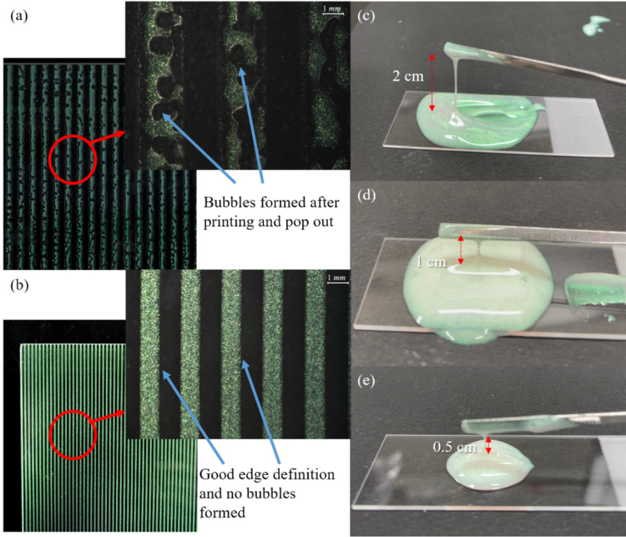
The stickiness of paste T with different concentrations of carrier vehicle T (60 and 90 wt%) was determined. The stickiness of Crystal ClearTM 220 mixed with 5 wt. % light interference pigment was tested on a glass slide using a spatula. The elongation of the paste before it broke apart was 2 cm, as shown in Fig. 4(c). Paste T, using a carrier vehicle T 60 wt% at part B, was tested on a slide glass, as shown in Fig. 4(d). The cohesion of the paste decreased, and the elongation decreased from 2 to 1 cm. Tmax which was activated on carrier vehicle T, created a three-dimensional (3D) network that resulted in different viscosities of paste T.
Paste T, using the carrier vehicle T 90 wt% at part B, was tested on a slide glass, as shown in Fig. 4(e). When the carrier vehicle T concentration increased, the viscosity of paste T increased; thus, the elongation of this paste decreased to 0.5 cm.
Carrier vehicle T contains a thixotropic agent, Tmax, which has weak cohesion and brittle failure because it obtains its elasticity from a sample spanning network that forms during activation but breaks down quickly following extension29). Along with the increase in Tmax which indicates an increase in viscosity, the elongation decreased32), as shown in Fig. 4(c) to Fig. 4(e). Even though the stickiness of paste T was reduced by introducing the carrier vehicle T, the base, which is Crystal ClearTM 220 itself, was a time-dependent liquid that became stickier with time.
Carrier vehicle E for color paste E was not a time-dependent paste, which differs from Crystal ClearTM 220, which becomes stickier with time after mixing. In fact, ethyl cellulose in carrier vehicle E is likely to produce distinctive internal cohesion and stickiness, making the mesh-emulsion screen connected through the stretched filaments of the paste to the substrate for a long time before snapping off33). However, Tmax in carrier vehicle E was found to be effective in suppressing the occurrence of sticky filaments, which is a major problem in paste T. The breakup length of the stretched filaments decreased with Tmax.
When color paste E was screen-printed, it separated immediately after printing without the occurrence of filaments, which would lead to bubbles in the flow to the separation region. The printing result using color paste E is shown in Fig. 4(b), where the printed lines have the same width as the opening on the mesh-emulsion screen with not only precise edge definition, but also without significant spreading. These improvements were achieved by balancing not only the viscosity but also the cohesion of colored paste E for screen printing. Moreover, because color paste E is not time-dependent, it can be stored for a while without noticeable rheological changes.
3.3 Front glazing of BIPV
Fig. 5(a) shows the case in which an OHP film with a screen-printed layer of color paste E was placed on a white background. In addition to green light interference pigments, it appears white because all the transmitted light through green light interference pigments is reflected from the white background and merges back with the reflected light from green light interference pigments, as illustrated in Fig. 3(b). Fig. 5(b) shows another case in which an OHP film with a screen-printed layer of color paste E was placed on a black background to mimic a solar cell. All the transmitted light through the green light interference pigments is absorbed by the black background, and only the light reflected from the green light interference pigments can be clearly seen.
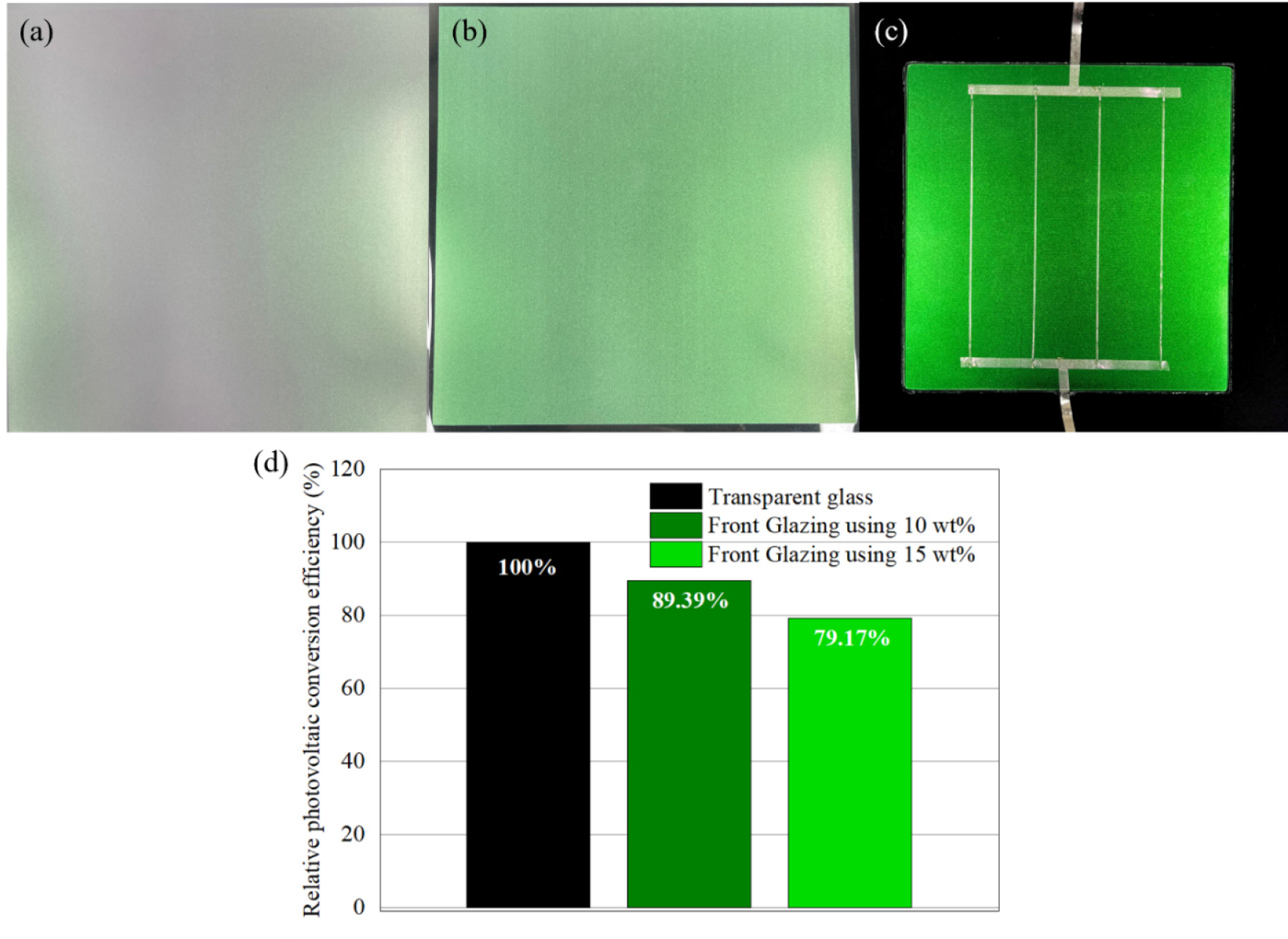
Fig. 5.
OHP films with the screen-printed layer of color paste E on (a) a white background; (b) a black background; (c) color silicon solar module after front glazing process using color paste E with 10 wt% green light interference pigment concentration; and (d) relative photovoltaic conversion efficiency results of color silicon solar module after front glazing process using color paste E with 10 wt% and 15 wt% of green light interference concentration
Fig. 5(c) illustrates a colored silicon solar module after the front glazing process using color paste E at a green light interference pigment concentration of 10 wt%. It exhibits a metallic and vivid green color, which increases the aesthetic value for generic glazing. The thickness of the printed layer affects the light absorption rate and the relative PV conversion efficiency. The average thickness of the printed layers using the color paste E with the green light interference pigment concentrations of 10 and 15 wt% was almost identical to be 24 µm. The transmittance measurement was performed and then averaged in the range of 300 and 1200 nm. The resulting transmittance of the printed layer was 85.84% with the green light interference pigment concentration of 10 wt% and 79.49% with the green light interference pigment concentration of 15 wt%.
The relative PV conversion efficiency results of the fabricated colored silicon solar modules at green light interference pigment concentrations of 10 and 15 wt% were 89.39and 79.17%, respectively, compared to those with transparent glazing. The higher transmittance of the printed layer will result in the higher relative PV conversion efficiency.
The relative photovoltaic conversion efficiency of a color silicon solar module with the green light interference pigment concentration of 10 wt% achieved in this study is comparable to such a color silicon solar module fabricated using a vacuum deposition process, which exhibits the relative photovoltaic conversion efficiency of approximately 90%9). Comparing to the previous results in Refs. 11, 12, and 13, where the relative photoconversion efficiency varies from 78% to 90%, the current relative photoconversion efficiency in this study is as high as 89.39% even using cheapest materials and the simple and economic screen printing technique
Based on the above results, the front glazing of BIPV using a color paste E at the green light interference pigment concentration below 10 wt% is anticipated to have a relative photovoltaic conversion efficiency, even higher than 90%.
4. Conclusion
In summary, a screen-printable paste for coloring the front glazing of BIPV was investigated. A light interference pigment, i.e., Lumina Green 9G30D, was used as a filler material for the screen-printable color paste. In the first trial, a two-part curable carrier vehicle, Crystal ClearTM 220, was tested as an ingredient of a screen-printable color paste, named paste T. Accordingly, it was found that the stickiness of paste T developed over time, and the screen-printed lines tended to have a poor edge definition with many bubbles formed in the flow separation region. It is also likely that the width of the printed lines are wider than the opening on the mesh emulsion screen, which indicates the unfavorable spreading of paste T. In the second trial, color paste E was tested, which consisted of carrier vehicle E and green light interference pigments at different concentrations ranging from 5-25 wt%. Unlike paste T, color paste E does not possess time-dependent stickiness, resulting in defect-free printed lines with a clear edge definition. The other advantage of colored paste E is that it enables a long period of storage without changing its properties.
Two different color pastes of E with green light interference pigment concentrations of 10 wt% and 15 wt% were screen-printed on the front glazing of BIPV, and a relative photovoltaic conversion efficiency as high as 89.39% was achieved at a green light interference pigment concentration of 10 wt%, which is comparable to that achieved using a vacuum deposition process for coloring the front glazing.
The screen printing method for coloring the front glazing of BIPV is considered a simpler and more economical method than the vacuum deposition process9). In this sense, it can be concluded that the in-house developed color paste E is suitable for the screen-printing method for coloring the front glazing of BIPV, which would be regarded as a breakthrough in the PV industry11).
